Tips on How to Reduce Stepper Motor Resonance
Tips on How to Reduce Stepper Motor Resonance
Motor vibration affects motor performance and motor life. Because every stepper motor has a resonance point, it is important to know the possible solutions to eliminate motor vibration from the start.
Stepper motors are designed in a way that allows the rotor to move to a discreet position. Rotor inertia allows the motor to overshoot its target slightly with every step. This causes the motor to oscillate before it gets to the target point. The continuous movement of the motor creates a frequency from these oscillations. The point at which the frequency matches the motor’s natural frequency, this oscillation becomes resonant and produces noise. If this resonance overpowers the magnetic field between stators and rotors, the motor can lose synchronization.
Electrical Vibration Reduction Methods
In this section, we will discuss a variety of methods that can be used to avoid resonance in your stepper motor. Note that everything from physical and electrical parameters through motor operational parameters can be adjusted. Each method discussed here should be considered seriously before making a final decision. Talking with stepper motor professionals is also a good idea and can speed you to the fastest solution for your specific application.
Since resonance happens at a particular speed of operation for your motor, avoiding commutating at that resonant frequency is the simplest way to eliminate the problem. There are applications where this approach is not possible but, when it is, avoiding the resonant speed will have a positive effect on performance as well.
Another technique to reduce oscillations is to micro-step at a finer step distance. The coil in the stepper motor energizes causing the motor to overshoot its position—due to a rapid flux change. Micro-stepping moves the stator flux more smoothly by reducing excitation energy to the coils. The result of this energy reduction is lower vibration and less noise, eliminating resonance. Micro-stepping is also the primary strategy used when an engineer wishes to increase stepper motor resolution.
For low-speed applications, whether for medical dispensing equipment or robotic motion, smooth operation can be acquired through reducing input current. By providing a lower current to the motor, you’ll produce less torque, which also reduces torque stiffness (dτ/dθ). As a result, less energy is produced to move the rotor. Make sure you have enough torque margin when using this technique so that you don’t instill other challenges to your design.
When the motor is running, resonance will induce an AC current into the motor winding. This induced current will interfere with the DC current going through the motor winding. By simply increasing inductance, the motor winding is able to either counteract the resonance or shift the resonance down in frequency.
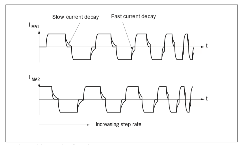
Often, fast current decay will help to reduce vibration and resonances. As the driver switches the current direction, the current decays in a transient manner causing residual current to interfere with the current set to the other direction. A slow current decay time will cause an increase in torque ripple, which will increase vibration. A fast current decay time will eliminate interference between the two current signals sent by the motor driver and reduce vibration during motor operation (see Figure 1).
Implementing R Windings with Two Phases On
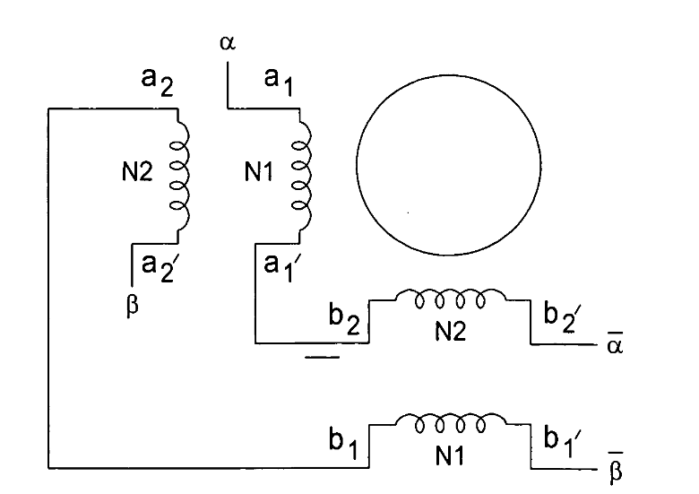
When using hybrid stepper motors, the stator operates using two phases where the winding coils are 90° apart from each other. For traditional stepper motor windings, the phase angles for each step is in increments of 45°: 0°, 45° 90°, 135°, 180°, 225°, 270°, 315°. When two phases are 45° from each other, both A and B phases are on. When two phases are 90° apart, only one phase is on.
Since the current distribution of one phase on mode and two phase on mode are different, the settling times of the two modes are also different. Resonance is likely to occur due to uneven settling times during each step.
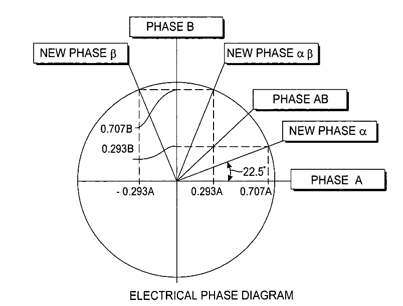
The R-winding motor has two coils per pole, each coil with different turns. The two sets of wires are wound in series with each other, but the end of the first coil is connected to the end of the second coil. This design allows the motor phase to shift 22.5 degrees, which results in reduced motor noise and vibration.
R windings eliminate the one-phase-on position by placing a new phase angle at: 22.5°, 67.5°, 112.5°, 157.5°, 202.5°, 247.5°, 292.5°, 337.5°. With two phases at all times, the driver will not supply 100 % of the current into one phase only. Having both phases on can make the settling time for each step identical, as a result, reducing resonance.
NOTE: The R winding solution was invented by Ted Lin (U.S Patent No. 6969930).
Implementing a T-connection is another way to reduce resonance. A T-connection forces the motor to keep two phases on at all times. The result of T-connection is similar to R-winding: having both phases on reduces the potential for vibration. Furthermore, the inductance level of a T-connection falls between a series and a parallel connection. This means that the T-connection can provide performance levels between series connection and parallel connection levels—higher torque at low speed compared to a parallel connection and higher torque output at high-speed operation compared to a series connection.
Increasing the number of phases, in general, can also reduce resonance. A motor with more phases will have a smaller step angle—similar to micro-stepping. The motor with more phases will reduce the excitation energy needed to rotate the rotor. As excitation energy is reduced, resonances are eliminated.
In this way, a two-phase motor will have 8 magnetic poles, while a five-phase motor will have 10 poles. The five-phase motor is designed with two poles per phase, so the rotor will move 1/10 of a tooth pitch to line up with the next phase. As a result, a five-phase motor has 500 steps per revolution and 0.72° per step. This higher rotation resolution requires less excitation energy to rotate the rotor; therefore, there is less overshoot of the rotor. If micro-stepping is implemented, a five-phase motor will operate with even finer resolution, and the vibration will be largely reduced.
Mechanical Vibration Reduction Methods
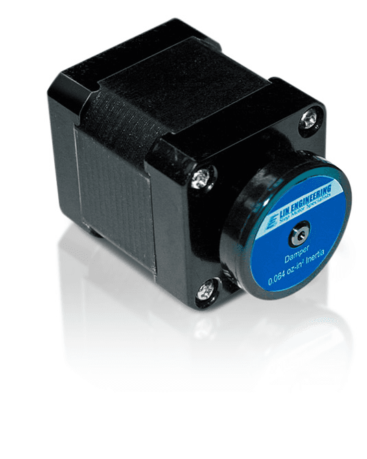
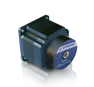
When it comes to adjusting the mechanical components of the motor to reduce vibration, installing a damper on the shaft of the motor can help a lot. Adding a mechanical damper also adds extra inertia to the shaft, which helps to absorb the vibration. This provides a highly stable damping effect. Adding a flange mount can also increase the absorption of vibration.
Another mechanical method used for damping vibration is to adjust the rotor inertia. The resonance range may change due to the damping effect of the load’s inertia. By adjusting the rotor inertia through the use of different materials, changing dimensions (eg. a longer rotor length), or providing a different rotor lamination profile (shown in Figure 4) you can shift the resonance point to reduce vibration.
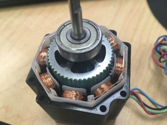
By adjusting the air gap between the rotor and stator tooth, a designer is able to increase or decrease torque stiffness. As mentioned above, the amount of torque the motor can generate will change, which results in a shift of the resonance point, allowing for vibration to be avoided.
If the motor is carrying a load—which is similar to a mechanical damper—the rotor inertia will be much greater and the oscillations from the motor will be reduced substantially.
Knowing how your stepper motor works, and what adjustments are available, can be a huge help when deciding on a solution that works for your application. When it comes time to focus on motion control during your design cycle, remember that you don’t have to select only from a company’s standard product offerings. If you have a specialized need, there are ways to get exactly what you want.
For more information:
News
Continue Reading

Selecting the Right Stepper Motor for Medical Applications
Medical applications often have the added concern that people’s lives may be in jeopardy if the equipment doesn’t work properly. Engineers working in this field of expertise must consider quality and longevity every step of the way. Therefore, when selecting a stepper motor for a medical device, engineers focus on the specific critical factors needed for the device prior to making a purchase. For example, a systolic pump may require high accuracy and a small footprint while a blood sampler used in a laboratory may need to be exceptionally quiet. As indicated, the requirements for stepper motors vary from device to device, yet there are several key factors that should always be considered.
Solutions to Eliminate the Over-Engineering of Motion Control Systems
In today’s motion control market, space, cost, and specifications battle it out to produce a product that can compete in a growing marketplace without failing early. One of the issues includes over-engineering based on the fact that engineers need to be sure that their project operates the way it needs to from the starting gate.