Design Accuracy Comparison 0.9° vs. 1.8° Stepper Motors
Design Accuracy Comparison 0.9° vs. 1.8° Stepper Motors
Oftentimes, when an engineer is selecting a step motor for his or her application, one important decision that needs to be made, is whether or not to choose a 0.9° or a 1.8° step motor. When making a decision of this magnitude, two factors will invariably come into play: performance and price. With the ever-increasing role of competition in today’s motion control industry, both performance and price are major difference makers in every decision.
In terms of performance the question is whether altering the way a 1.8° step motor operates will, in fact, produce a 0.9° type motor performance. There is a widespread belief that using a 1.8° motor at half stepping will produce the same accuracy as a 0.9° motor at full stepping. With accuracy and smooth motion being the main advantages of using 0.9° motors, this belief leads some to think that the 1.8° motor at half stepping will be sufficient and available at a lower price. Furthermore, the fear of losing torque with a 0.9° motor is also an issue. While these skepticisms are valid, both mechanical and design explanations and theories might put your mind at ease.
First, let’s take a look at what makes a step motor accurate. One of the main contributing factors in a step motor’s accuracy is torque stiffness. Torque stiffness, which is derived by the number of rotor teeth a step motor has, controls the accuracy of a step motor. The higher the torque stiffness, the less the motor oscillates, or springs back and forth, with each step it takes. Therefore, higher torque stiffness results in higher accuracy.
| Torque Stiffness (dT/dTheta) | 0.9° Step Motor | 1.8° Step Motor |
|---|---|---|
| * where T = the holding torque value (oz-in) | 280T | 470T |
Looking further at the rotor design of 1.8° and 0.9° motors, it can be seen that a 1.8° motor has 50 rotor teeth whereas a 0.9° step motor has 100 rotor teeth. This alone gives 0.9° motors higher torque stiffness and thus, higher accuracy. In comparison, with low torque stiffness, the 1.8 motor is more likely to spring back and forth with each step, making it less accurate than the 0.9 motor. The common belief that stepping a 1.8° step motor at half stepping produces accuracy comparable to a 0.9° motor at full stepping is inaccurate because doing so will force the step motor to move in increments where it naturally would not have gone to. Also, this increases the step resolution, which will invariably increase the step error within this motor because the increase will make it difficult for the motor to keep up with such precise steps.
Now the question is whether or not the enhanced performance of a 0.9° motor is worth the extra money. In order to make a better decision, we must first note that not all 0.9° motors are made and perform equally. In fact, there are three mechanically different 0.9° motors that can be purchased each with their own distinct performance capabilities and benefits.
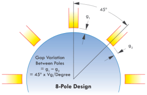
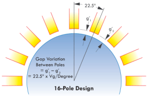
The mechanical difference between the three types of 0.9° motors is their stator design and the relative air gap between the rotor and stator. Depending on its design, the stator and relative air gap of a step motor have a drastic effect on accuracy, operating speed range, and torque production capability. The air gap between the rotor and stator is always non-concentric. No step motor manufacturer can produce a perfect outside diameter of the rotor and inside diameter of the stator in perfect concentricity within each other. There is a definite air gap variation apparent in every motor. This air gap variation has a severe effect on the motor’s step accuracy. Knowing this, let’s compare the number of poles in the first two 0.9° step motor designs. Typical 0.9° motors contain either 8 poles or 16 poles within their respective stators. For an 8 pole design, the angle between each pole is 45°. A 16 pole design, on the other hand, has a 22.5° angle between each pole that allows for less variation of the air gap between poles.
An 8 stator pole design could have an air gap variation of up to twice as much as compared to the 16 pole design even if both motors were built with the same manufacturing capabilities.
However, there are additional drawbacks to each stator design. Due to space constraints of the 16 pole design, manufacturers are only able to wind half as many turns when compared to an 8 pole design. Therefore, inductance is reduced by about half. Low inductance is mainly good for high-speed applications. Torque will also be lower in the 16-pole design due to this constraint in space. With less space, there are fewer windings per pole (turns per coil). Typical 1.8° step motors use the 8-pole stator design, which explains for the higher torque but lower accuracy when comparing it to a 0.9° step motor.
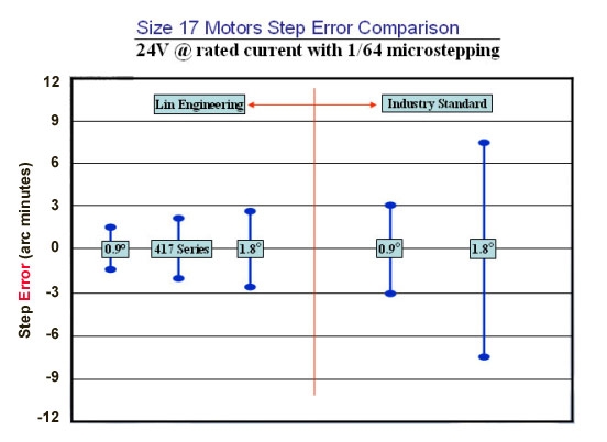
When choosing between the 8 stator pole and 16 stator pole motor designs, customers will inevitably be choosing between a high torque motor with less accuracy and a lower torque motor with higher accuracy. The third mechanically different 0.9° step motor, created and patented by Lin Engineering, fills the void left between the 8 and 16 stator pole designs.
Although Lin Engineering’s 417 series step motor has 12 stator poles, it is still able to step at 0.9° angles because its rotor contains 100 teeth. As mentioned earlier, the number of teeth within a step motor’s rotor determines the step angles that it is able to achieve. The motor’s stator design then determines its accuracy and torque capabilities. Since the rotor has teeth, the stator must also have teeth in order for the motor to be able to step at 0.9° angles. The stator, however, can not contain 100 teeth because the air gaps between the poles have to be accounted for. Below is a comparison of the number of teeth per pole for the 8, 12, and 16 stator pole designs.
| 0.9° Motor Stator Design | 8-POLE | 12-POLE | 16-POLE |
|---|---|---|---|
| # of Teeth per Pole | 18 | 7 | 5 |
| Total # Teeth on Stator | 80 | 84 | 80 |
As shown above with the 12 pole design, more teeth can be added to the stator due to simple mathematics. The higher number of teeth allows for added torque and, because there are more poles, the air gap variation is not as large as the 8 pole design making the step accuracy better as well.
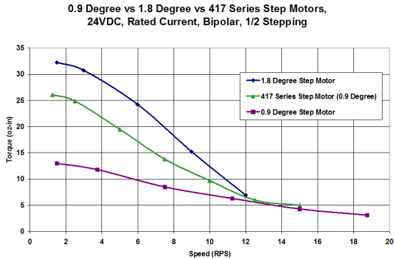
When step motors are designed into your next application, it would be wise to choose accordingly: traditional 0.9° steppers for high speeds and high accuracy, 1.8° steppers for more torque and less accuracy, and the 417 series 0.9° steppers for both torque and optimal accuracy. For more information, contact Lin Engineering at sales@linengineering.com.
News
Continue Reading
What is R-Winding and How Does it Affect My Stepper Motor?
Most step motor users are familiar with Series and Parallel connections; now, the patented R-Winding (U.S. Patent No. 6,969,930) has been created to reduce noise and vibration for lower-torque applications.
AMPS Phase vs. AMPS Peak
Step Motor Terminology got you stumped? Lin Engineering explains the differences between Amps/Phase and Amps Peak Current.