Part Number
R725
Unit Price:
$249.00
Inventory:
10 Available in 2 Business Days
Ships:
2 Business Days
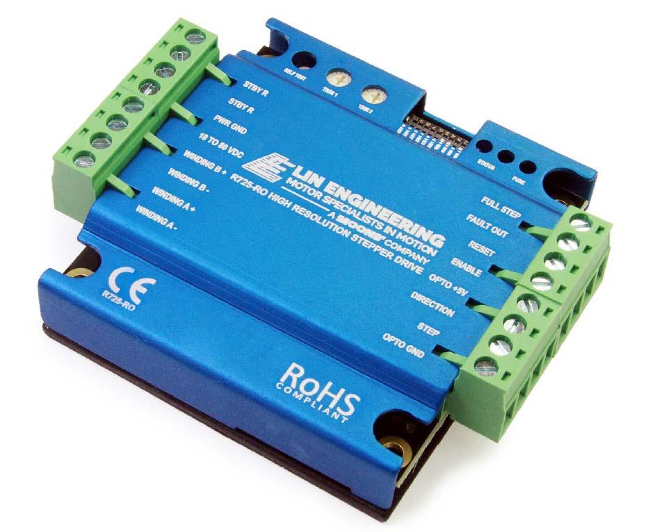
R725 SERIESR725STEPPER DRIVER

Quick Facts
R725 Drivers & Controllers
- Operates from 18 to 80V
- Selectable Driver Peak Current Ranges: 0.1 to 7 Amps
- Cooler running temperature
- Next-generation resonance compensation.
- Extra resolution choices.
- Push Button Self-Test.
- Resolution upscaling at low speeds.
- User adjustable standby current.
Key new features of the R725
1. Cooler running temperature
Upgraded and over-rated power section components reduce heating by up to 30% compared to previous revisions.
2. Next-generation resonance compensation.
Midband instability and resonance is compensated for using all new algorithms, eliminating resonant frequencies at the midband completely, with no adjustment necessary. The R725 will run a motor smoothly out of the box.
3. Extra resolution choices.
Ranging from half-step to 256-microstep resolution, a stepper motor can be run with resolution of up to 51,200 pulses per revolution.
2 | 5 |
4 | 10 |
8 | 18 |
16 | 50 |
32 | 100 |
64 | 180 |
128 | |
256 |
4. Push Button Self-Test.
Testing and tuning stepper motors can now be done simply with an onboard self-test button. Simply pushing and holding this button down will run the motor CW and CCW at low speed, allowing easy tuning for motor resonance with the onboard adjustment trimpot.
5. Resolution upscaling at low speeds.
Every microstep is further broken down into higher interpolated microsteps to increase motor smoothness at extremely low speeds. The resolution upscaling will change depending on the microstep resolution chosen via DIP switch to be sure your motor is getting the smoothest possible operation at all times.
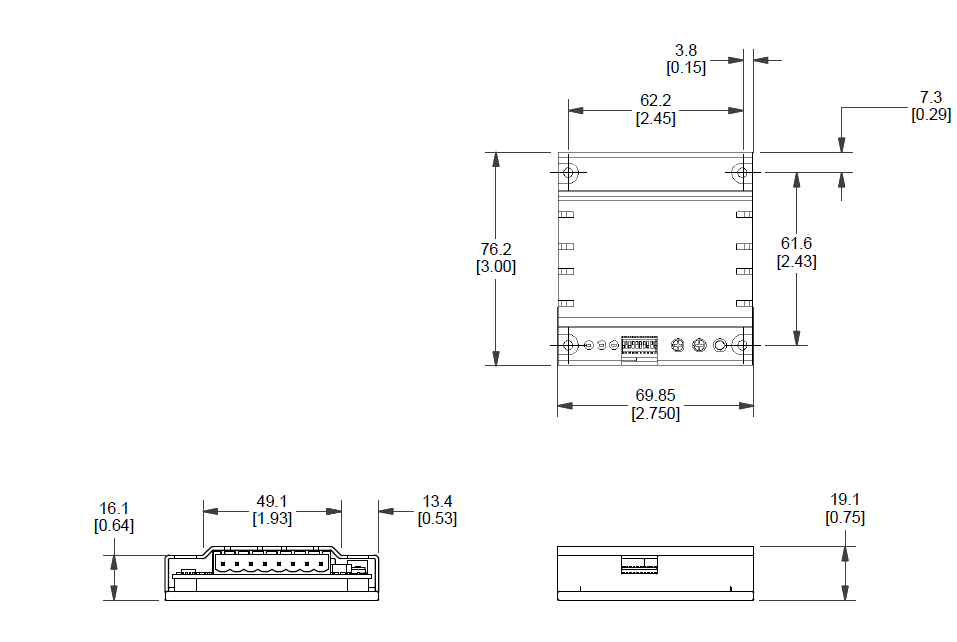
Dimension

Pin Outs
Connector 1
| PIN# | FUNCTION | DETAILS |
| 1 | GND | Signal Ground |
| 2 | STP | The edge of step pulse on this input advances the motor one increment. The size of the increment is dependent upon the settings of the resolution. |
| 3 | DIR | This input is used to change the direction of the motor. |
| 4 | +5V | This +5VDC input is used to supply power to the isolated logic inputs. |
| 5 | ENABLE | This input is used to enable/disable the output section of the driver. When in a Logic HIGH state (open), the outputs are enabled. |
| 6 | RESET | When LOW, this input will reset the driver (phase outputs will disable). |
| 7 | FAULT OUTPUT | This output indicates that a short circuit condition has occurred. This output is active LOW. |
| 8 | FULLSTEP OUTPUT | This output indicates when the driver is positioned at full step. This output can be used to count the number of full steps the motor has moved, regardless of the number of microsteps in between. |
Connector 2
| PIN# | FUNCTION | DETAILS |
| 1 | REDUCE CURRENT | Phase Current Reduction Adjustment |
| 2 | CURRENT | Phase Current Adjustment |
| 3 | GND | Power Ground. The ground, or return, of the power supply is connected here |
| 4 | V+ | Motor Supply Voltage. +18V to +80VDC |
| 5 | ~PHB | ~PHASE B of the stepping motor |
| 6 | PHB | PHASE B of the stepping motor |
| 7 | ~PHA | ~PHASE A of the stepping motor |
| 8 | PHA | PHASE A of the stepping motor |
Electrical Specifications
- INPUT VOLTAGE: +18 to 80
- DRIVE CURRENT(PEAK): 0.1 to 7 Amps
- ISOLATED INPUTS: Reset, Enable, Step, Direction
- STEP FREQUENCY (MAX): 2.5 MHz
Related Products
Get the motor you need
Just fill out a Request for a Quote form, and tell us about your application and your needs. One of our applications specialists will review your request, and provide you with a quote promptly.
