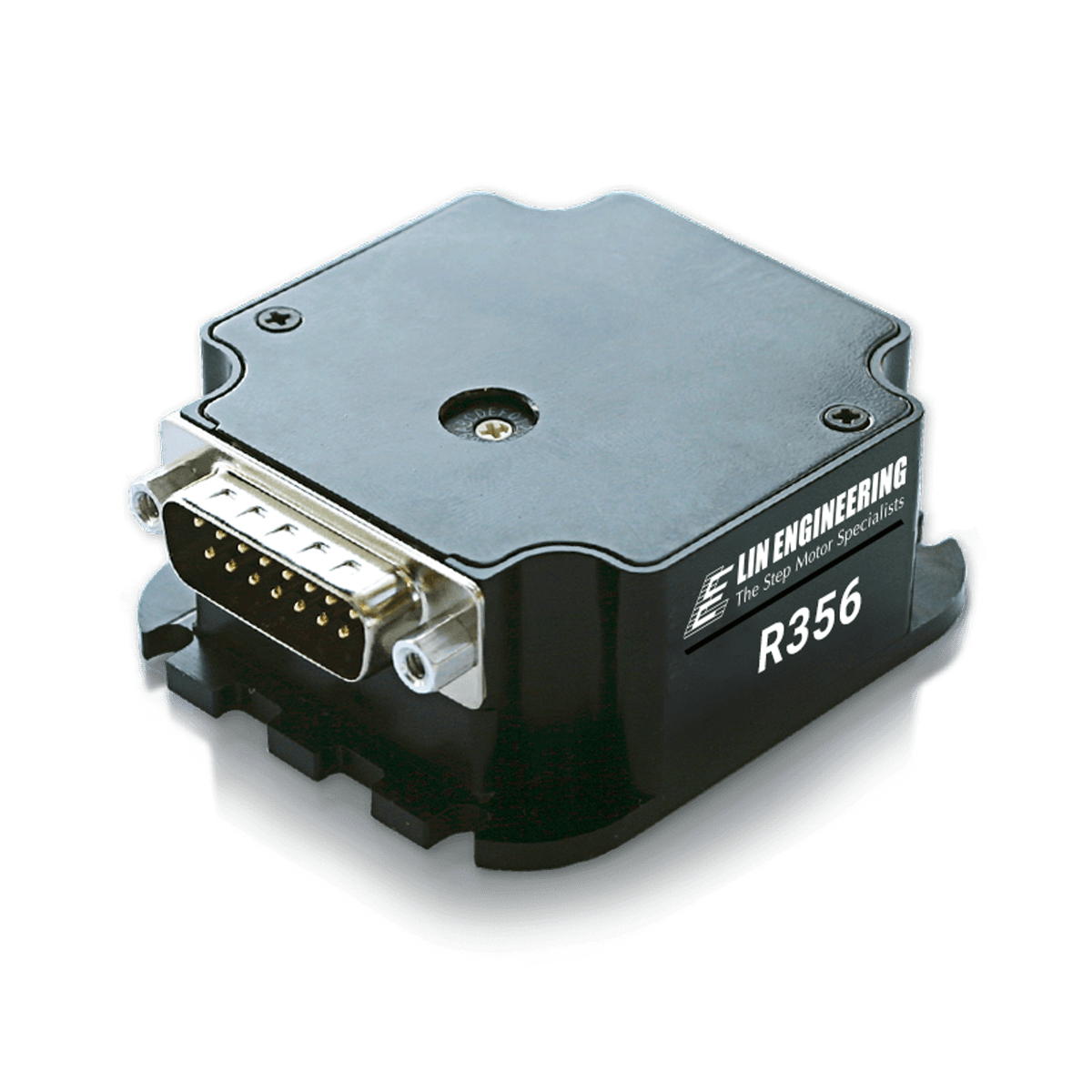
Part Number
R356
Unit Price:
$449.00
Inventory:
0 Available
R356 SERIESR356STEPPER DRIVER + CONTROLLER
Quick Facts
R356 Drivers & Controllers
- Input Voltage of +12 to 40 VDC
- Phase Current Ranges from 0.2 to 3.0 Amps Peak
- Full step, 1/2, 1/4, 1/8, 1/16, 1/32, 1/64, 1/128, 1/256
- RS485 Communication. (Optional Converter Cards Available)
- 2 User Configurable Digital I/O’s
- 2 Dedicated Inputs: 1 Optical Sensor for Homing, 1 Switch Closure to Ground
- Fully Programmable Ramps and Speeds
- Software Selectable Hold and Move Currents
- Stand Alone Operation with No Connection to PC
- Stores up to 16 Different Programs at Once with 4 kBytes of Mem
Options
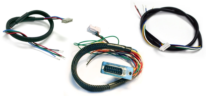
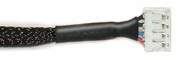
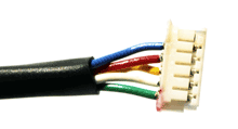
Each R356 comes with the following cables (Lin part number 4634140205144, 4634140205208, and 4634140205260):
4-pin cable | DB-15 cable with white 3-pin connector | 6-pin cable
• The R356 is a fully intelligent controller and driver in one. Commands can be issued from any serial terminal program, such as HyperTerminal, or from Lin Engineering’s Graphical User Interface, LinControl. (have LinControl link to the download section)
• Commands are simple and intuitive. This communication is compatible with devices that use the Cavro DT or OEM protocol.
• The R356 controller is also capable of stand alone operating with no PC. It can execute a pre-programmed string of commands upon Power up. Commands include nested loops, wait statements, halt commands, software selectable currents, speeds, acceleration, microstepping, and more.
The Designer’s Kit (sold separately) enables first time users to become well acquainted with the options of R356 Controller/ Driver. Converts the drivers default RS-485 communication into RS-232.
RS232 Designer’s Kit (Lin part number: DRV RS232KIT) Includes:
• RS-485 to RS-232 Converter Card
• An Optical Sensor
• Red Switch Push Button
• 3-Pin Cable

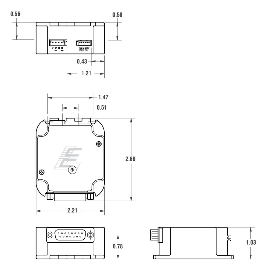
Dimension
Pin Outs
PIN ASSIGNMENTS
* Inputs are labeled 1, 2, 3 and 4 for programming the ‘Halt’, ‘Skip’, and
special mode ‘n’ commands.
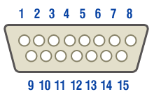
| PIN NUMBER | COLOR | FUNCTION | I/O ALTERNATIVE FUNCTION |
|---|---|---|---|
| 1 | Green | Power Ground | |
| 2 | Black | 1A On/ Off Output | |
| 3 | Yellow Green | Direction Input | |
| 4 | Yellow | +5 VCD Input for Opto Isolated STEP and DIR | |
| 5 | Orange | Input | 2/Jog Input |
| 6 | Yellow/ White | Internal Power for Opto Sensor | |
| 7 | Orange/ White | Input (Opto Input) | 3/Opto Input |
| 8 | Black/ White | RS485 A | |
| 9 | Red | +12V TO 40V POWER | |
| 10 | Blue | 1A ON/ OFF Output | |
| 11 | Blue/ White | Step Input | |
| 12 | Green/ White | Signal Ground | |
| 13 | White | Input | 1/Jog Input |
| 14 | Red/ White | Input | 4/Opto Input |
| 15 | Brown | RS485 B |
CONNECTORS
| Color | Function |
|---|---|
| Red | A+ Phase |
| Blue | A- Phase |
| Green | B+ Phase |
| Black | B+ Phase |
A mating connector for the motor is also provided.
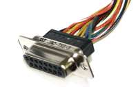
DB-15 connector is provided with the controller/driver
This should ideally be used with a US digital E2, E3, or E5 encoder.
| Pin Number | Color | Function |
|---|---|---|
| 1 | Green | Ground |
| 2 | White | Index |
| 3 | Yellow | Ch B |
| 4 | Red | +5 VDC |
| 5 | Blue | Ch A |
| 6 | --- |
DB-6 connector
Downloads
R356 Configured Datasheet (PDF)
Documentation
Examples
Lab View and Visual Basics Examples (ZIP)
Software
Lin Command 32 bit (ZIP)
Lin Command 64 bit (ZIP)
Get the motor you need
Just fill out a Request for a Quote form, and tell us about your application and your needs. One of our applications specialists will review your request, and provide you with a quote promptly.