Part Number
R256
Unit Price:
$399.00
Inventory:
10 Available in 2 Business Days
Ships:
2 Business Days
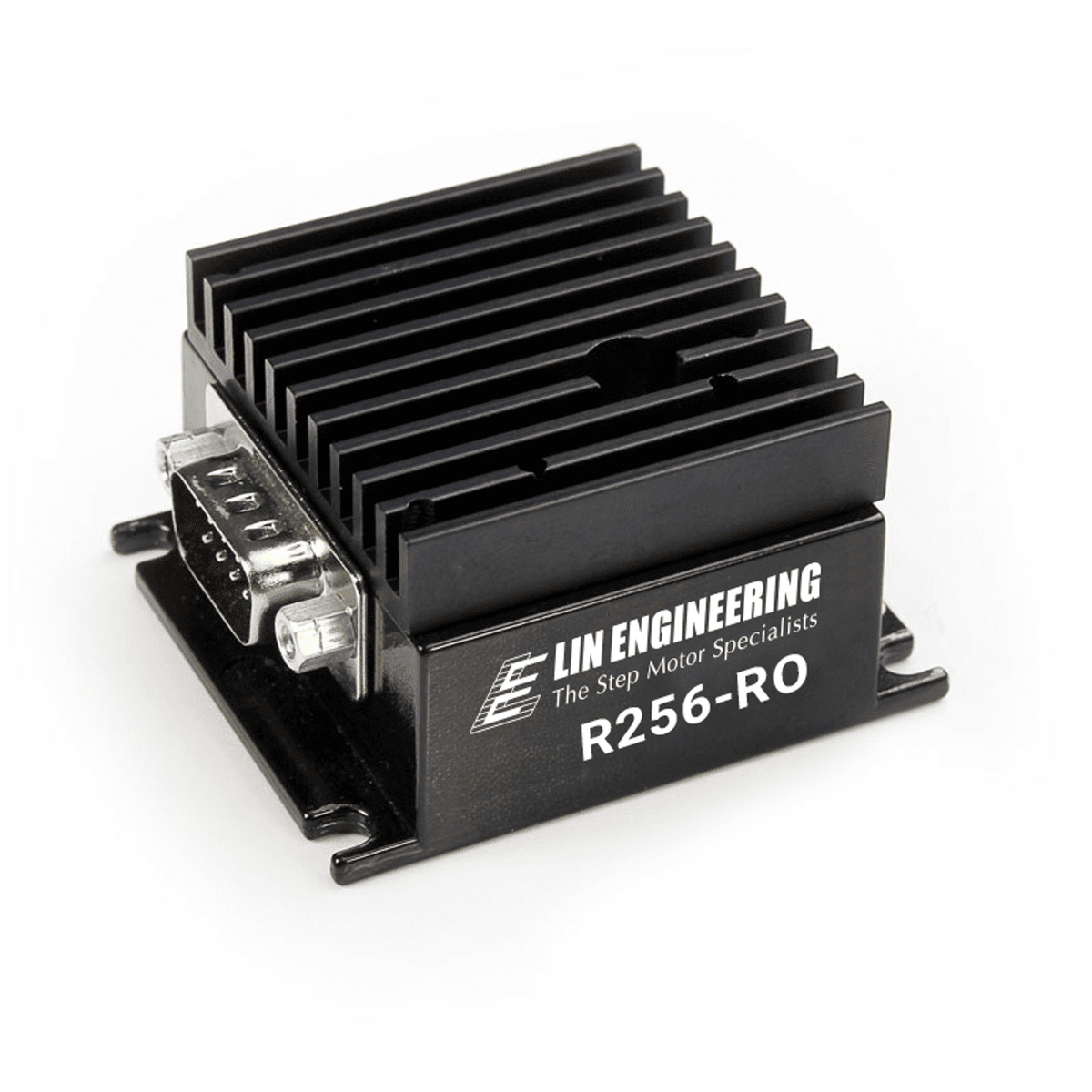
R256 SERIESR256STEPPER DRIVER + CONTROLLER
Quick Facts
R256 Drivers & Controllers
- Input Voltage of +12 to 40 VDC
- Phase Current Ranges from 0.2 to 2.0 Amps Peak
- Full step, 1/2, 1/4, 1/8, 1/16, 1/32, 1/64, 1/128, 1/256
- RS485 Communication with Optional Converter Cards Available
- 2 User Configurable Digital I/O’s
- 2 Dedicated Inputs: 1 Optical Sensor for Homing, 1 Switch Closure to Ground
- Fully Programmable Ramps and Speeds
- Software Selectable Hold and Move Currents
- Stand Alone Operation with No Connection to PC
- Stores up to 16 Different Programs at Once with 4 kBytes of Mem
Options
Each R256 comes with the following cables (Lin part number 4634140205166 and 4634140205144):
DB-9 cable with white 3-pin connector | 4-pin cable

- The R256 is a fully intelligent controller and driver in one. Commands can be issued from any serial terminal program, such as HyperTerminal, or from the Windows Application Program
- Commands are simple and intuitive. For example, A1000 will move a stepper motor to Absolute Position 1000. This communication is compatible with devices that use the Cavro DT or OEM protocol.
- The R256 controller is also capable of stand alone operating with no PC. It can execute a pre-programmed string of commands upon Power up. Commands include nested loops, wait statements, halt commands, software selectable currents, speeds, acceleration, microstepping, and more.
The Designer’s Kit (sold separately) enables first time users to become well acquainted with the options of R256 Controller/ Driver. Converts the drivers default RS-485 communication into RS-232.
RS232 Designer’s Kit (Lin part number: DRV RS232KIT) Includes:
• RS-485 to RS-232 Converter Card
• An Optical Sensor
• Red Switch Push Button
• 3-Pin Cable

Dimension

Pin Outs
| PIN NUMBER | FUNCTION |
|---|---|
| 1 | +12 to 40VDC |
| 2 | I/O |
| 3 | RS485B |
| 4 | RS485A |
| 5 | Switch Closure to GND (In) |
| 6 | Power Ground |
| 7 | Opto Sensor Phototransistor (In) |
| 8 | I/O |
| 9 | Opto Sensor LED(Power Out) |
A DB-9 male connector provides power and control connections. Mating connector provided.
Electrical Specifications
- OPERATES FROM +12 to 40 VDC
- SELECTABLE PHASE CURRENTS FROM 0.2 TO 2.0 Amps Peak
- ISOLATED INPUTS: I/O, Switch Closure to Ground, Opto Phototransistor
- STEP FREQUENCY (MAX): 16.77 MHz
- STEPS PER REVOLUTION (1.8° MOTOR): 200, 400, 800, 1600, 2000, 3200, 5000, 6400, 10000, 12800, 25000, 25600, 50000, 51200
- MICROSTEP RESOLUTIONS (1.8° MOTOR): Full step, 2X, 4X, 5X, 8X, 10X, 16X, 25X, 32X, 50X, 64X,125, 128X, 250X, 256X
| FUNCTION (Command) | DESCRIPTION |
|---|---|
| Running Current (m) | 30% of 2.0 Amps |
| Holding Current (h) | 10% of max current of 2 Amps |
| Step Resolution (j) | 256x |
| Top Velocity (V) | 305175 pps (microsteps/sec) |
| Acceleration (L) | L=1000, 6103500 usteps/sec^2 |
| Microstep smoothness (o) | 1500 |
| Outputs (J) | both are turned off, J0 |
| Baud Rate | 9600 bps |
Downloads
R256 Configured Datasheet (PDF)
Documentation
Examples
Lab View and Visual Basic Examples (ZIP)
Software
Lin-Command-32-bit (ZIP)
Lin-Command-64-bit (ZIP)
Get the motor you need
Just fill out a Request for a Quote form, and tell us about your application and your needs. One of our applications specialists will review your request, and provide you with a quote promptly.