Lin Engineering
Featured product media

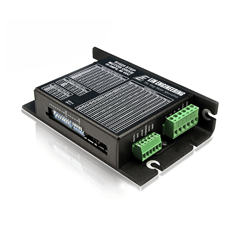
R1025 SERIES
R1025
STEPPER DRIVER

Features and Benefits:
  • Operates from +12 to 80 VDC
  • Selectable run currents from 0.8 to 10 Amps Peak Holding and Running Torque
  • Step Resolutions from Full step, 2x, 4x, 5x, 8x, 10x, 16x, 25x, 32x, 50x, 64x, 100x, 125x, 128x, 250x, 256x Microstepping
  • Optically isolated inputs that can sink and source (3 to 24 VDC, 16mAmps)
  • Selectable Damping modes for smooth motion
  • Easy to configure without connecting to PC, utilizes DIP switches (Run and hold current, Step resolution, Smoothness setting)
  • Operating temperature of -40C to 85C
  • Operates in ambient temperature of -20C to 50C

Out Puts

FUNCTIONPIN NAMEDESCRIPTIONELECTRICAL SPECS.
POWER/MOTORGNDGND. Connect the negative end of Power Supply hereGND
 +VDCPower. Connect Positive end of Power Supply here. DO NOT EXCEED MAX VOLTAGE RATING OF 80VDC!Voltage Input: 12 - 80VDC
 B-Phase B Bar Motor ConnectionPhase currents from 0.8 to 10A Peak Current Chopping Frequency: 22KHz
 BPhase B Motor ConnectionPhase currents from 0.8 to 10A Peak Current Chopping Frequency: 22KHz
 A-Phase A Bar Motor ConnectionPhase currents from 0.8 to 10A Peak Current Chopping Frequency: 22KHz
 APhase A Motor ConnectionPhase currents from 0.8 to 10A Peak Current Chopping Frequency: 22KHz
LOGICGNDLogic GNDGND
 COM (Input)Opto Common input. Used to Optically Isolate the Input when a separate supply is connected. Connecting the +5VDC will make the Inputs Functional but the Inputs will NOT be Isolated. Note COM needs to be powered either by a separate supply or the +5VDC Pin in order for the Input/Outputs to function.Voltage: 3 - 24 VDC
Max Current: 20mA
 DISABLE (Input)Used to Disable drive. Active Low. A closed connection to GND will Disable the drive. This is a Sink or Source InputVoltage: 3 - 24 VDC
Max Current: 20mA
 STEP (Input)The Step output from a Pulse Generator is Input into this pin. Both an NPN and a PNP type PLC can be used for this input. Refer to Connection Diagrams for helpVoltage: 3 - 24 VDC
Max Current: 20mA
 DIR (Input)Used to switch Direction of motor. Active Low. A closed connection to GND will change direction. This is a Sink or Source Input.Voltage: 3 - 24 VDC
Max Current: 20mA
 +5 VDC (Input)Internal +5VDC Output. If Optical Isolation is not desired then it can be connected to COM Pin. DO NOT USE FOR EXTERNAL CIRCUITRY!Voltage: 5 VDC
Max Current: 80mA
Content image

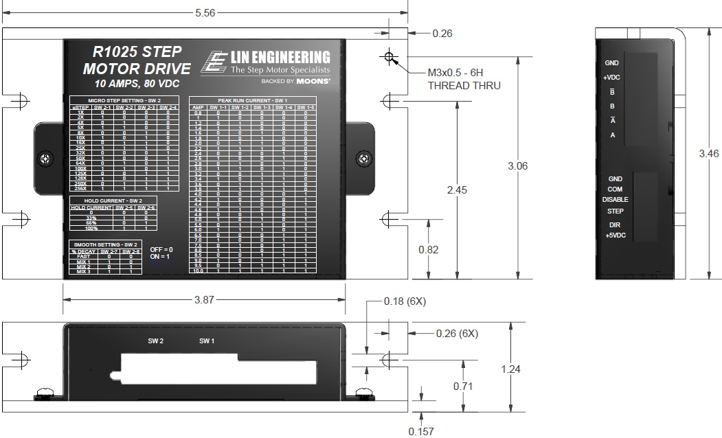
Dimension

Content image

Electrical Specifications

• Operates from +12 to 80 VDC • Selectable phase currents from 0.8 to 10.0 Amps Peak
• Isolated inputs: Step, Direction, and Disable • Step frequency (max): 1.0 MHz
• Steps per revolution (1.8° motor): 200, 400, 800, 1600, 2000, 3200, 5000, 6400, 10000, 12800, 25000, 25600, 50000, 51200}
• Microstep Resolutions (1.8° motor): Full step, 2X, 4X, 5X, 8X, 10X, 16X, 25X, 32X, 50X, 64X,125, 128X, 250X, 256X
• Operating Temperature: -20°C to +85°C

DEFAULT SETTINGS

Direction of RotationCounterclockwise
Step Resolution8x step (3200 steps/rev)
Run CurrentMotor's rated current or up to 5 Amps Peak
if motor is rated for 5 or higher
Holding Torque0.5 Amp/Phase
Smoothness Setting2
Step Signal SensingSenses on the Rising Edge or positive edge
Disable ActiveLow or oV signal to disable unit

Related Products

Downloads

R1025 Configured Datasheet (PDF)
Download

Documentation

R1025-Manual-v1.20 (PDF)
Download