Request a Quote
R525P SERIESR525PSTEPPER DRIVER + CONTROLLER
Quick Facts
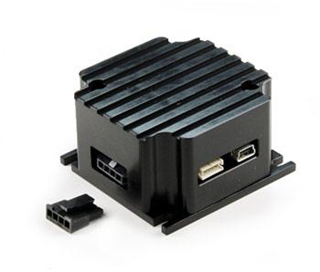
R525P Drivers & Controllers
R525P Drivers & Controllers
Features and Benefits:
- Operates from +12 to 48 VDC
- Software selectable run currents from 0.1 to 5.0 Amp Peak
- Software selectable hold currents from 0 to 5.0 Amp Peak (in 0.05 Amp increments)
- Step Resolutions from Full step to 256x Microstepping
- Communicating using RS485 and USB
- Operates in both Open loop and Closed loop modes
- Programmable analog input to change velocity and position.
- Programmable digital output for feedback.
Options
Each R525P-RO comes with the following 4 cables in order for you to get up and running. No Designer’s Kit is required in order to operate one unit.

R525P GUI SETUP

Dimension

Pin Outs

P1 MOTOR CONNECTOR PIN-OUTS
| PIN | FUNCTION | COLOR |
|---|---|---|
| 1 | Motor Phase A | RED |
| 2 | Motor Phase A- | BLUE |
| 3 | Motor Phase B | GREEN |
| 4 | Motor Phase B- | BLACK |

P2 ENCODER CONNECTOR PIN-OUTS
| PIN | FUNCTION |
|---|---|
| 1 | Channel B |
| 2 | 5V Input |
| 3 | Channel A |
| 4 | Index |
| 5 | Ground |

P4 I/O CONNECTOR PIN-OUTS
| PIN | FUNCTION | COLOR | DESCRIPTION |
|---|---|---|---|
| 1 | +5V out | Red/White | 5 VDC out |
| 2 | Opto COM | Yellow | This is a 5VDC input in order to optically isolate the logic signals (step, direction, disable pins). If no isolation is required, you can connect this pin to Pin 1, the 5VDC output. |
| 3 | Disable pin | Blue | Enable/Disable pin. When pin is low, or touching Pin 12 Ground, the driver is disabled. If left alone (high), driver is enabled |
| 4 | RS485/A | Black/White | Communication line for RS485 connection. Used for dasiy chaining multiple units |
| 5 | Ground | Green/White | Power Supply Ground |
| 6 | POWER+VE | Red | Motor Power Supply Voltage, +12 to 48VDC |
| 7 | Direction | Orange | Direction input. Default connection will rotate the motor CCW. If this input is low, or touching Pin 12 Ground, rotation will be CW. |
| 8 | Analog input | White | This input can take a potentiometer |
| 9 | Step input | Blue/White | Step pulse input. The step clock input will receive a clock pulse input (TTL squarewave signal, 0 to 5VDC), where one pulse will move the motor one step |
| 10 | RS485/B | Brown | Communication line for RS485 connection. Used for dasiy chaining multiple units |
| 11 | Output | Black | Via the GUI, user can choose to disable the unit, change motor direction, close upon fault, toggle when index is detected on the encoder, close when motor is stalled, moving or holding |
| 12 | Ground | Green | Signal ground, also known as digital ground |

Electrical Specifications
- OPERATES FROM +12 to 48 VDC
- DRIVE CURRENTS (per phase): 0.1 to 5.0 Amps Peak
- ISOLATED INPUTS:Step,Clock, Direction, and disable
- STEP FREQUENCY (Max): 1 MHz
- STEPS PER REVOLUTION (1.8° MOTOR): 200, 400, 800, 1600, 2000, 3200, 5000, 6400, 10000, 12800, 25000, 25600, 50000, 51200
- MICROSTEP RESOLUTIONS (1.8° MOTOR): Full step, 2X, 4X, 5X, 8X, 10X, 16X, 25X, 32X, 50X, 64X,125, 128X, 250X, 256X
- OPERATING TEMPERATURE: Heatsink maximum temp 85°C