Selecting the Right Linear Actuator to Improve Operating Efficiency
Selecting the Right Linear Actuator to Improve Operating Efficiency
Selecting the appropriate linear actuator can be quite the ordeal – and selecting the wrong one could dramatically reduce the efficiency of your application and shorten its lifespan. Learn about the different types of linear actuators, how to select the right one, and which services can help make the decision as simple as 1-2-3!
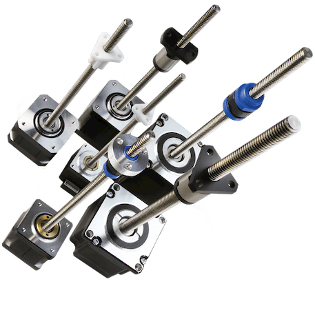
Step motors are used in applications where precise rotary motion is needed. Step motor driven linear actuators, on the other hand, are used in applications where precise linear motion is needed. Basically, the precise rotary motion that a step motor delivers is translated into linear motion with the use of lead screw and a nut.
There are few different designs of linear actuators you need to consider when selecting an actuator for your design; each design has its advantages and disadvantages, and serves unique purpose, so let’s examine each design:
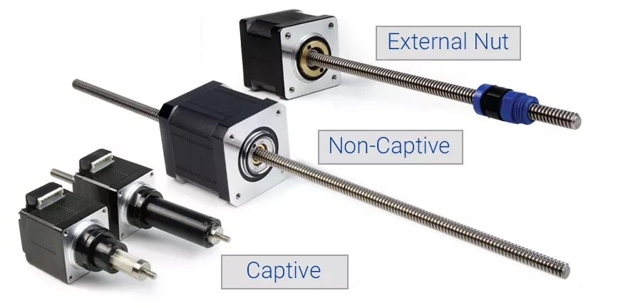
External Nut

The most popular design of linear actuators, the external nut configuration is simple, compact, and offers a high level of design flexibility. In the external nut configuration, the shaft of the stepper motor is replaced with a lead screw. In a typical application, the motor is fixed in position and an apparatus is attached to the nut. As the lead screw rotates, the external nut travels along the length of the screw, providing linear motion.
The length and the pitch of the lead screw are highly customizable, making the external nut configuration useful for a wide variety of applications. Numerous mounting options paired with the many types of nuts available help tailor this particular linear actuator to best fit a user’s specific situation. In addition, the external nut configuration helps achieve greater acceleration and maximum speeds than other configurations while also offering greater efficiency in terms of power consumption.
There are a few limitations to consider that could make the use of the external nut configuration challenging within certain applications. The length of a lead screw in this particular configuration, for example, is limited. If the end of the screw is unsupported within an application, you run the risk of experiencing flex. The longer the lead screw is, in other words, the more flex it will have. Additionally, as the screw rotates, you may experience vibration. This is especially true at higher speeds. Excessive vibration can contribute to lower accuracy and increased noise generation as well as a whole host of other problems.
The maximum force this application can handle is also limited, meaning that you should carefully consider how much strength you’ll need before selecting the external nut configuration.
Non-Captive
In non-captive configuration, the nut is incorporated into the motor’s rotor. As the rotor rotates, it creates linear motion by passing the leadscrew through the shaft. In this instance, your apparatus can be attached in one of two ways: directly to the motor, or to the leadscrew.
When the apparatus is attached directly to the motor, the leadscrew is usually rotationally fixed. As the rotor rotates, it moves the motor along the length of the lead screw providing linear motion. Since both ends of the lead screw are supported, the maximum length of the lead screw can be greater than that of an actuator with external nut. This is a popular option for applications that require longer travel. This configuration can also handle more force than external nut design.
Another advantage to consider is that the motor provides more mass and, therefore, more damping power. This means that you experience less vibration, which often translates to quieter and more accurate motion. Non-captive design can also be desirable when a rotating lead screw could potentially conflict with other components or prove to be hazardous. Since the lead screw is fixed in position, less moving parts are exposed.
The biggest disadvantage to this design is the space requirement. The motor tends to have larger diameter than a simple nut with a flange, for example, and because they often need to be guided, extra space needs to be allocated for motor leads. The leads in question tend to be considerably longer than in other configurations, and it must travel along with the motor.
The mass of the motor can also limit the acceleration and maximum operating speed of your application, and certain power efficiency is sacrificed because more mass needs to be moved.
Another popular option is to attach an apparatus to the lead screw while keeping the motor fixed in position. This removes the need for long leads and lead tracking. Most of the benefits can be retained if the apparatus can be supported from both ends of the lead screw.
Captive
The third common configuration is the captive linear actuator. In this design, a screw is attached to a splined shaft. That shaft is prevented from spinning through the use of a splined socket attached to the face of the motor. Linear motion is achieved while each component is rotationally fixed and where no rotation is visible from outside. This is a good choice if your application lacks a mechanism which prevents either the lead screw or the nut from rotating.
Because the length of the splined shaft in a captive linear actuator has a mechanical limit, its travel distance is usually limited to just few inches. Something else to keep in mind is that the length of the motor is considerable, and the length of the splined socket needs to be proportional to the length of splined shaft. The screw also protrudes from the back of the motor, and the length of that screw is proportional to the maximum stroke the actuator can achieve.
News
Continue Reading
Inaccuracies with Motors+Drivers | Who is the Culprit?
Is your step motor and driver contributing to the inaccuracy of your system? When it comes to precision in the motion control industry, there are many important factors that contribute to inaccurate steps. As a total system, engineers must become knowledgeable of their step motor as well as their driver/controller units.

Stepper Motor Medical Application Requirements
When selecting a step motor for an application in the medical industry, many factors need to be considered. Although the requirements for step motors vary from application to application, some requirements should be generally considered as a rule of thumb. This article will help walk you through some of those requirements and how Lin Engineering can help.