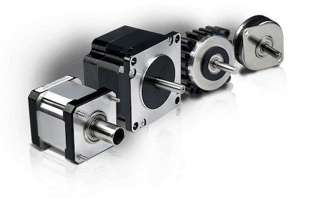
Hybrid Stepper Motors
WHAT IS A HYBRID STEPPER MOTOR?
A hybrid stepper motor is a motor that moves in precise angles, called steps, by converting a series of electrical pulses into rotational motion. They will not produce continuous motion from a continuous input voltage, and it will stay at a particular position as long as the power is “on”. Hybrid step motors are controlled with the use of discrete electrical pulse signals. Each pulse will rotate the step motor shaft by a fixed angle called a “step”. Lin Engineering hybrid stepper motors have several different step angles to choose from (0.45°, 0.9°, 1.8°).
If the pulses are carried out in a specified sequence, the motor will spin continuously; the speed can be controlled by the rate at which the pulses are sent. These natural step angles allow a step motor to be accurately positioned without the accumulation of error. The step motor produces output torque from the interaction between the magnetic field in the rotor and in the stator. The magnetic field strength is proportional to the amount of current applied to the windings as well as the amount of turns in the windings.
Hybrid stepper motors are used in many different applications that require accurate and repeatable positioning and speed control. They are used in industries such as: Aerospace, Automation & Packaging, Medical, Printing & Engraving, Security & Surveillance Systems, Semiconductors, and Solar & Green Technology.
ADVANTAGES OF HYBRID STEPPER MOTORS
- High reliability with little maintenance
- Open loop operation - No feedback is required for position or speed control
- Non-cumulative positional error
- Inherently more fail safe than servo controlled motors
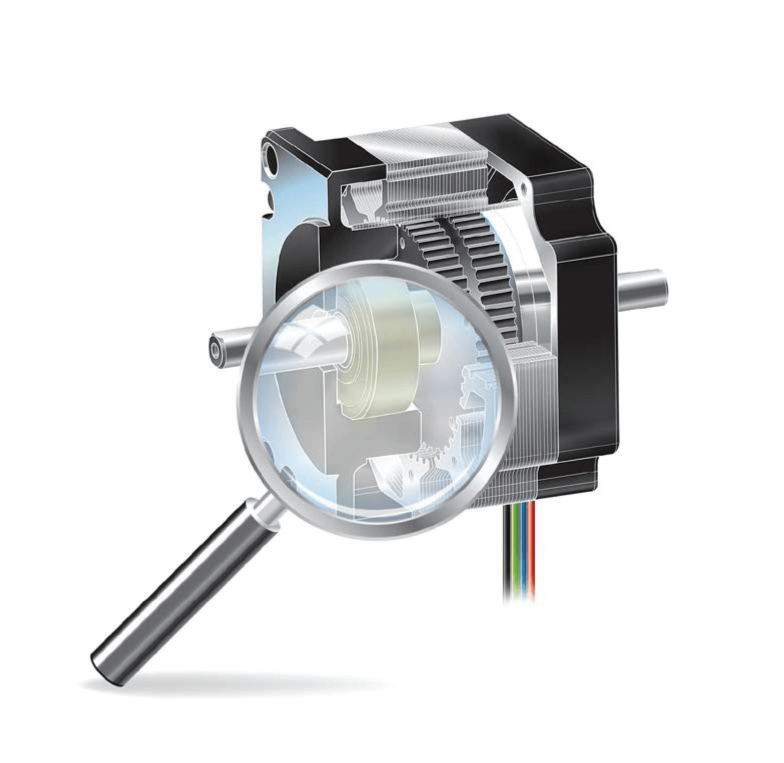
BASIC FEATURES AND CONSTRUCTION OF A HYBRID STEPPER MOTOR
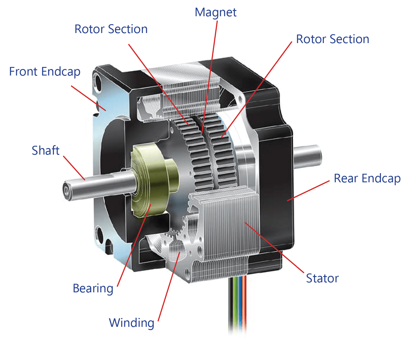
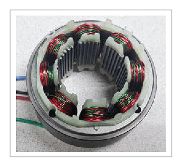
A hybrid stepper motor consists of a permanent magnet sandwiched between the two rotor halves (causing axial polarity), which make up the spinning part of the motor, placed into a stator housing where the stator coils of wire make up the different motor phases. Lin hybrid stepper motors have two phases, where each phase has four coils. The phase is magnetized where the A and A- phases (or B and B-)are magnetized at the same time, so that both A phases are magnetized as one pole, and both A- phases are magnetized as the opposite pole because the winding direction of the A phase is opposite the winding direction of the A- phase.
The rotor is connected to the motor shaft, which gives the output rotation and torque of the motor when voltage and current pulses are applied to the motor windings. The bearings on either side of the rotor allow for smooth rotation with little friction and wearing. The bearings are placed into their designated spaces in the front and rear endcaps, which allow for concentricity of the rotor inside the stator. Perfect alignment of the rotor and the stator is very important because the airgap between them, where the motor torque is generated, must be equal on all sides and is only a few nanometers wide - thinner than a strand of hair.
HOW DOES A STEPPER MOTOR WORK?
When power is connected to the leads, a pulse of current is applied into the motor windings and turns “on” a phase, which causes the rotor to rotate until magnetic reluctance is minimized and the rotor settles into a stable magnetic position. For a bipolar motor, this pulse of current fills up the first-phase coils with charge and creates a magnetic field for each of the 4 first-phase coils, which magnetizes the stator teeth in front of the charged coils. All four coils attract oppositely charged rotor teeth while repelling similarly charged rotor teeth on the opposite end of the rotor. The rotor teeth on the north and south ends of the rotor are offset slightly from each other, so one charged stator tooth can pull at an oppositely charged rotor tooth on one end of the rotor while repelling two similarly charged rotor teeth on the other end of the rotor until the motor settles into a detent position. This creates a “pushing and pulling” effect that increases the motor torque.
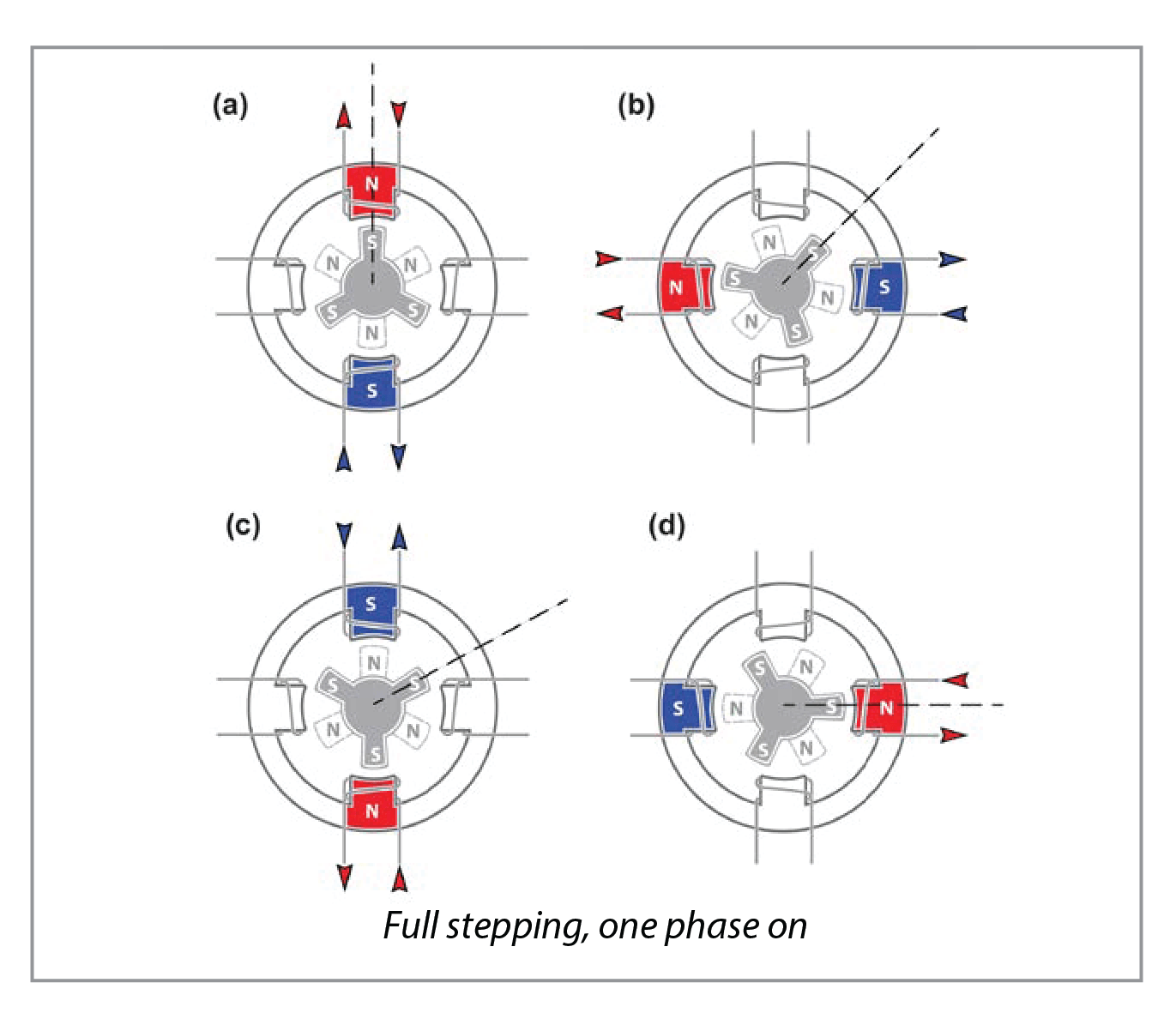
The torque required to move the rotor from this stable position is called the holding torque. Turing one phase on will hold the rotor in one position, called a detent position. The charge is then turned off in the first set of coils, and turned on in the next set of coils, magnetizing the next set of stator teeth. The rotor then rotates until the next rotor tooth aligns with one of the magnetized stator teeth. The rotor is now moved one step angle to the next detent position. This “on and off” current flow causes the rotor to rotate one precise step angle, and this movement is repeated with each input pulse.
Half stepping happens when the first pulse magnetizes the first phase, then the next pulse magnetizes the first phase and the second phase, then the next pulse magnetizes only the second phase, etc. This allows the rotor to move in smaller increments at a time, allowing for smoother and more continuous motion with less resonance and only slightly less torque.
DIFFERENT WINDINGS OF HYBRID STEPPER MOTORS
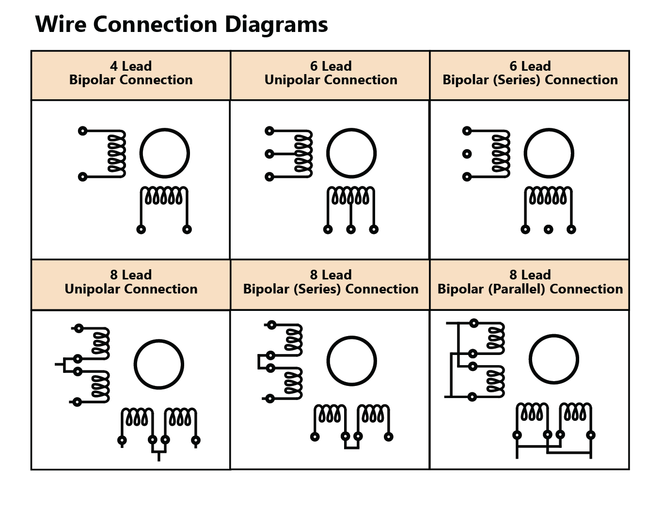
Unipolar
Unipolar winding has two windings per phase, and can reverse the magnetization of the stator coils without reversing the direction of the current. It has a center tap for each phase, which can be used to change the wiring to supply current to the opposite half of each coil.
This runs the motor in the reverse direction without changing the direction of the current. Therefore, a Unipolar only uses 50% of the windings because half of the windings are reserved for the forward direction only and half are used for the reverse direction only. It has 6 or 8 leads, generates less torque than a bipolar motor because it can only use half the coil at a time, and has a simpler/cheaper drive system because the current does not need to change direction.
Bipolar Half Coil
Bipolar winding has a single winding for each phase, so the current needs to be reversed to reverse the magnetic pole of a coil. Therefore, it uses 100% of the windings. It generates more torque and has a more complex/expensive drive system. Bipolar windings can also be wired in parallel or series, depending on torque required and speed of the motor.
Bipolar Parallel
Bipolar parallel winding has two coils per phase that are wired together in parallel. The parallel windings allow a higher torque output at higher speeds, has the same inductance as a single half-coil winding, has half of the resistance of a half-coil winding, and requires twice the current to match the ampere-turns of a series wound bipolar motor. This winding is ideal for high speed applications that require a lot of torque.
Bipolar Series
Bipolar series winding has two coils per phase that are wires together in series. The series windings allow a higher torque output at lower speeds because the number of turns, which is proportional to torque, is effectively doubled. The series winding has four times the inductance value of a single half-coil or parallel winding, twice the resistance of a half-coil winding, and requires half the current of a parallel winding to match its ampere-turns.
HYBRID STEPPER MOTOR CURRENT WAVEFORMS
Most step motors step 1.8° per full step. (Lin step motors are also available in 0.9° and 0.45° step angles). If a motor is driven in the full step mode (using a 1.8° as an example), the current waveform of one of the phases will look like the following:
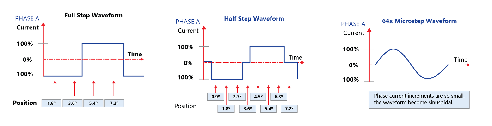
100% current refers to the motor’s phase current or rated current (Amps/Phase). (Microstepping is a feature of the driver, dividing the currents into finer increments)
8 POLES vs. 12 POLES HYBRID STEPPER MOTOR DESIGN
Taking a Closer Look:
2-Phase Hybrid Stepper Motors can be constructed in a variety of ways internally. Although there are a number of different components within a stepper motor that have a large impact on performance, it can be argued that the most important component is the stator.
The stator can be designed in such a way where there are 8 poles, 12 poles or even 16 poles. The poles are where the wires are wound around, essentially resulting in the windings of the motor. The mechanical difference between the three types of stator designs is their relative air gap between the rotor and stator. The air gap between the rotor and stator is always nonconcentric. No step motor manufacturer can produce a perfect outside diameter of the rotor (rotor OD) and inside diameter of the stator (stator ID) in perfect concentricity within each other.
There is a definite air gap variation apparent in every motor. This air gap variation has a severe effect on the motor’s step accuracy. Knowing this, let’s compare the number poles in the first two 0.9° step motor designs. Typical 0.9° motors contain either 8 poles or 16 poles within their respective stators.
In the Figures 1a and 1b below, you can see that the angle between each pole on the 8-Pole hybrid stepper motor design is 45°. The 16-Pole design has a 22.5° angle. As a motor steps, it is holding in one position where the stator pole is aligned with the rotor. It then moves to the next pole to align with the rotor. From one pole to the next, if the air gap is slightly smaller or larger, you will see this variation in the form of inconsistent step accuracy, vibration and resonance, and inconsistency in torque.
Notice in Figure 1a, that g1 and g2 can potentially be very different compared to Figure 1b. The closer your poles are, it minimizes the variation differences from step to step. However,
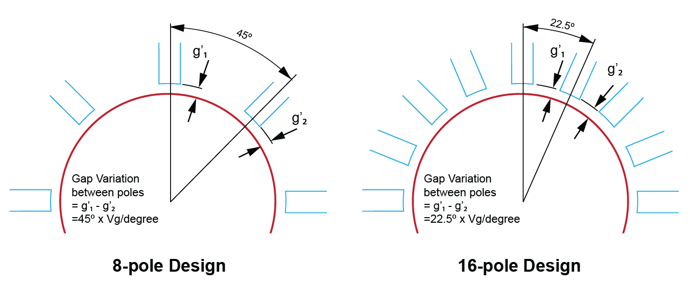
there are drawbacks to each stator design. Due to space constraints of the 16 pole design, there are less winding per pole (turns per coil) which results in lower torque output. The 8 pole design doesn’t have this issue so there is not a relative drop off in torque. Even though an 8 pole design provides adequate torque, it could also have up to twice as much air gap variation when compared to a 16 pole design which results in less accuracy.
When choosing between 8 and 16 stator pole designs, customers inevitably had to choose between a lower torque motor with high accuracy or a high torque motor with less accuracy; for a time, that’s all that was available. Lin Engineering then created and patented a 12 pole stator design in order to fill in this performance gap. The 12 pole design became a great hybrid to the traditional designs as it was able to provide a suitable amount of torque while still maintaining high step accuracy
Among a variety of other reasons, the unique 12 pole design allowed Lin Engineering to capture the majority of the high accuracy and low noise/resonance market; to date, Lin Engineering is the highest volume manufacturer of the 0.9° hybrid stepper motor. More recently, Lin Engineering has taken the 0.9° stepper motor design to the next level with the patented Signature Series Technology. For example, the G5709 is a NEMA 23, 0.9° hybrid stepper motor that utilizes the 12 pole design and is infused with Signature Series Technology. This allows for the ultimate performance: high accuracy without sacrificing an inordinate amount of winding space.
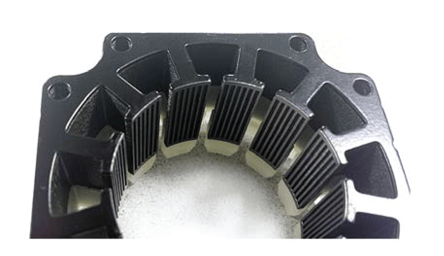
How is this done? Let’s discuss the number of teeth on the stator. In a 0.9° stepper, there are 100 teeth on the rotor. Therefore, the number of stator teeth must be less than 100. Each extra tooth that you can squeeze into the stator design will give you more torque, inherent in the design, regardless of winding space.
The standard NEMA 23 0.9° stepper design contains 8 poles and 10 teeth per pole, totaling 80 teeth on the stator. The new G5709 motor contains 12 poles and 7 teeth per pole, totaling 84 teeth on the stator. Even though there is less winding space in a 12 stator pole design when compared to an 8 stator pole design, the increase in the number of teeth make up the difference.
With the G5709, you can get the accuracy, smoothness, and low vibration that you need without sacrificing torque.
STEP ACCURACY IN HYBRID STEPPER MOTORS
Best Way to Measure:
This technical article describes the most accurate way to describe step error that is most meaningful to the step motor user. The traditional way to specify step accuracy is in the form of a percentage by taking the full step error divided by the fundamental step angle of the motor. Let’s understand this and see how we can convince the industry to measure in terms of actual step error in degrees or better yet, in arc-minutes.
The traditional method of using percentage error stems from applications that frequently used motors at full-stepping in order to generate the best torque. However, in today’s industry, most applications operate at ½ stepping or micro-stepping. Step accuracy during full stepping no longer serves the purpose for today’s needs.
Step accuracy is inherent in a motor’s mechanical design. Micro-stepping increases the step resolution but not step accuracy. Micro-stepping a motor without good step accuracy does not provide smooth motion.
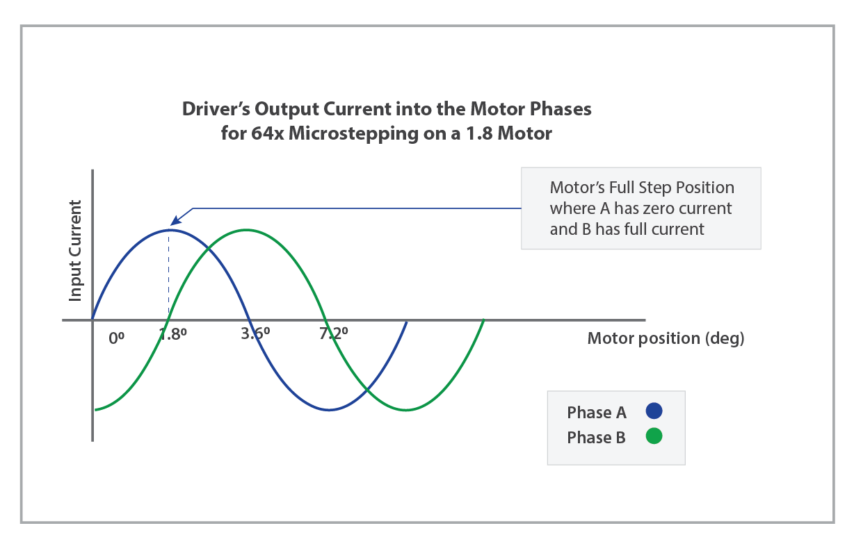
Micro-stepping is controlled by the motor’s current ratio of the phases from the motor driver. The current ratio table is built based on a sinusoidal torque curve of step motors. See Graph 1 for a visual understanding of how microstepping works in regards to the input current to the two motor phases.
A motor that does not have a sinusoidal torque curve cannot follow the micro-stepping position. Since not every motor can produce a sinusoidal torque curve and the current ratio cannot be perfect from electronics control, a step motor cannot maintain the same accuracy as full stepping when compared to micro-stepping.
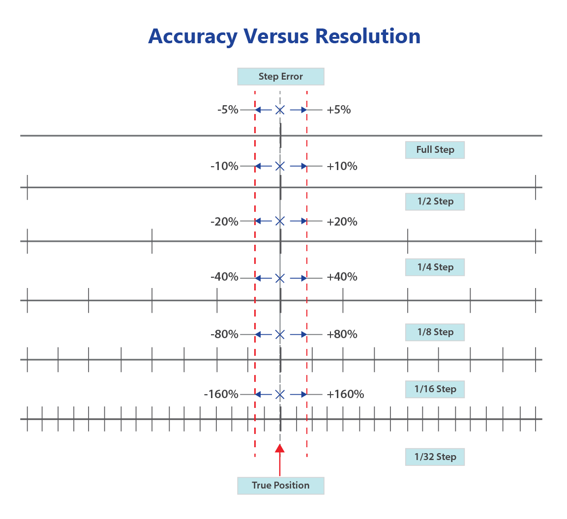
Laboratory studies show that the step error may double or quadruple from full stepping to 1/64 stepping. A motor with good step accuracy at full stepping does not automatically provide good step accuracy at micro-stepping. Assuming that a perfect micro-stepping motor can keep the absolute step error regardless of the number of micro-stepping, 5% step error of a full step becomes 10% of a ½ step and 20% of a ¼ step. The percentage of the micro-step size will be up to 100% or more at a high number of micro-stepping. Therefore, reporting the step error at the % of full step is meaningless. See Graph 2 on the next page.
For instance, a standard step motor with +/- 1.5% step error of full step seems to be very good. It turns out to be +/- 4.2% (not 3% = 2 × 1.5%) errors of half step, and it becomes +/- 180% (not 96% = 64 × 1.5%) errors of 1/64 step at micro-stepping.
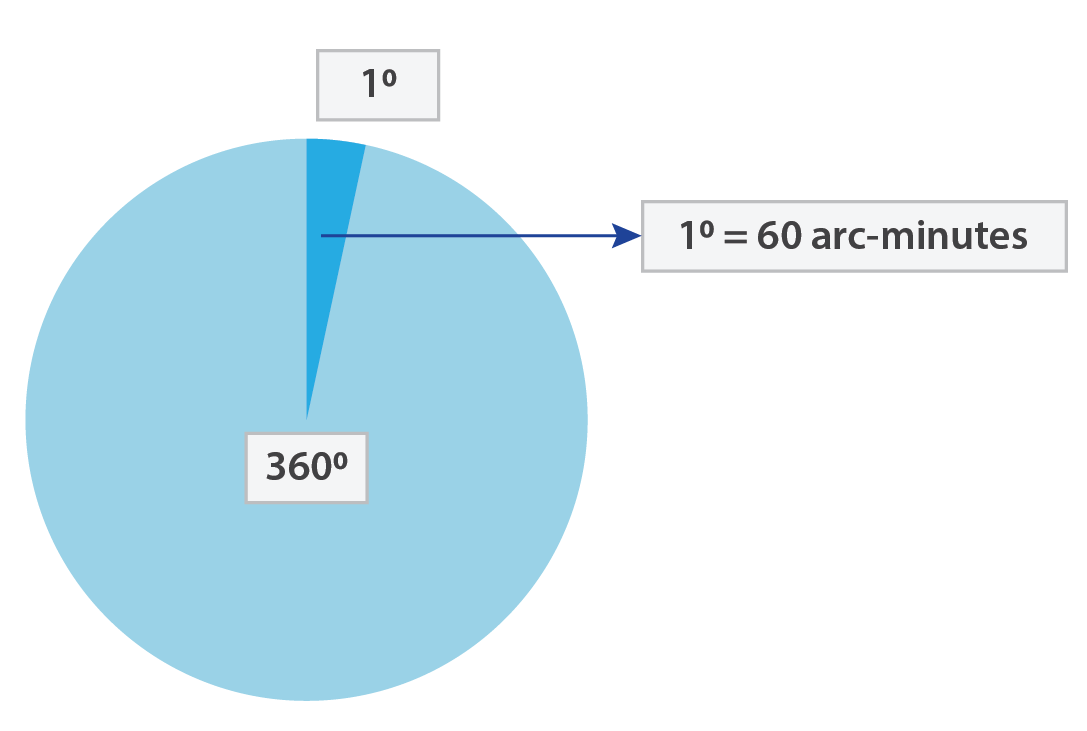
Not knowing if the application uses ½ stepping, ¼ stepping, 1/8 stepping, 1/16 stepping, 1/32 stepping or 1/64 stepping, Lin Engineering redefined the step accuracy in arc-minutes based on 1/64 stepping (1 arc-minute is 1/60th of a degree). Because anything higher than 1/64 stepping has very little impact to the application in terms of smooth motion & noise. Meanwhile, a motor with good step accuracy at 1/64 stepping automatically provide good step accuracy at larger stepping than 1/64.
As a step motor user, we do care about the absolute step error based on our operating mode. Specifying step error as the % of full-step is meaningless, because the percentage of error gets much worse at higher micro-stepping. Lin’s 0.9° step motor specifies +/- 1.5 arc-minutes error at 1/64 stepping. It has +/- 0.4 arc-minute error at full step and +/- 0.6 arc-min error at half-stepping. 0.4 arcminute translates to 0.37% of 1.8° or 0.72% of 0.9°. It is much better than the industry standard of 1.5% of 1.8°, which is considered good for most step motor manufacturers. It is the time for Lin to share with everyone about what truly good step accuracy is.
Microstepping has been clearly defined as full-stepping, ½ stepping and ¼ stepping in the industry. Rather than saying 1/8 stepping or finer stepping, most engineers started saying 8 micro-stepping or more micro-stepping. Here is the table for a clear communication:
Stepping Modes
- Full Stepping = 1 Microstepping
- 1/2 Stepping = 2 Microstepping
- 1/4 Stepping = 4 Microstepping
- 1/8 Stepping = 8 Microstepping
- 1/10 Stepping = 10 Microstepping
- 1/16 Stepping = 16 Microstepping
- 1/32 Stepping = 32 Microstepping
- 1/64 Stepping = 64 Microstepping
- 1/128 Stepping = 128 Microstepping
- 1/256 Stepping = 256 Microstepping
The step errors can range from ±1.5 arc-minutes up to ±5 arc-minutes for size 17, 0.9-degree motors, and from ±3 arc-minutes up to ±12 arc-minutes for 1.8-degree motors during micro-stepping. Lin motors perform the best in both the 0.9-degree and the 1.8-degree arenas. It is because we design a sinusoidal torque motor. This is one of the reasons that Lin’s 0.9-degree motors are the most popular in precision motion applications.
An accurately superior motor is also mechanically more efficient. Vibration, from inaccurate stepping wastes energy and results in a net loss of power from the electro-mechanical system. High accuracy motors deliver more energy to the load than more powerful but less accurate motors.
The next time you see step error defined as a percentage, first be sure you know how it is defined. Is it a percentage of the full step or at a certain microstepping? Furthermore, what’s the actual error in degrees? The most effective way to call out step error is in arc-minutes (or degrees), and to specify the error at a specific step resolution, like 16x or 64x microstepping.
REFERENCES
Step Accuracy: A measure of a step motor’s maximum deviation from it’s desired or indicated position. Step accuracy is noncumulative or the deviation found in any number of steps is no greater than the maximum deviation for a single step.
Microstepping: An electronic control technique that proportions the current in the motor’s windings to provide additional inter-mediate positions(steps) between poles. Produces smooth rotation and high positional resolution.
Arc-minute: Arc-minute a unit that is used to describe very fine increments of degrees. It is 1/60th of a degree, or 0.01667°. Conversely, 60 arc-minutes equals 1°.
Why Choose Lin Engineering?