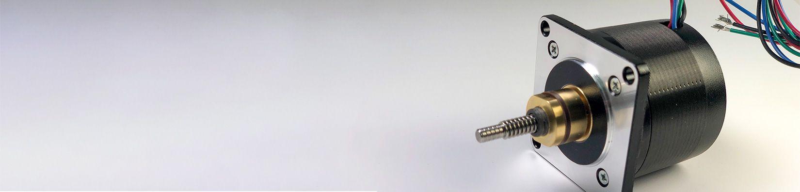
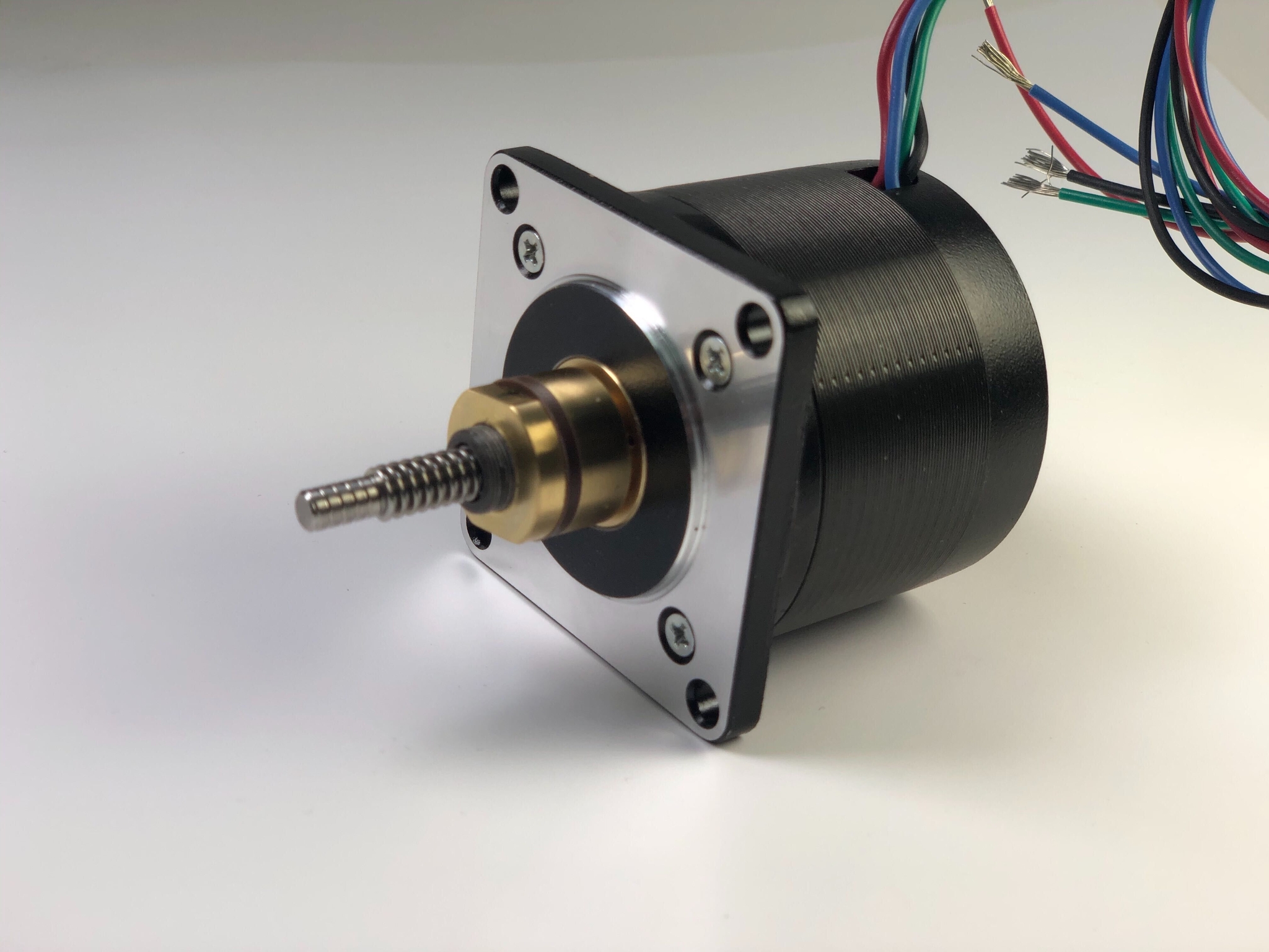
ln23 high speed captive actuator
A customer reached out to us with a unique problem on hand that had no obvious off-the-shelf solution. They required a captive linear actuator that needed to move a significant load at very high speed. On top of that, the linear actuator needed to deliver accurate and repeatable motion. Since the motor was to be manufactured in large volumes; ease of setup, installation, and overall system cost was important.
The customer had prototyped and experimented with a few off-the-shelf solutions before reaching out to us, but none of the solutions delivered the required performance. Their prototypes proved to be inaccurate, imprecise, or not fast enough. Additionally, the required velocity exceeded the critical speed of most motors sampled, which introduced unwanted vibrations into the system, further reducing accuracy and precision.
Furthermore, most available options also proved to be too expensive or too cumbersome to setup and install, which would increase the overall cost of the system beyond the budgetary allotment. A non-standard solution was needed, and this is when they decided to approach us.
Our Engineers quickly got to work exploring various ways to deal with the problem. It became obvious that in order to increase accuracy, repeatability and speed; an anti-backlash mechanism was required. As well, it would need a balanced configuration of a motor and a leadscrew to be successful.
Selecting and optimizing the motor and the leadscrew
In order to achieve the right performance characteristics required for the specific application, the first step is to select a proper mix of components. Mainly pairing the right motor with the right leadscrew. The motor needs to provide the required torque at a specific speed, while the leadscrew needs to provide the proper linear force at a specific speed. It’s all a balancing act.
Leadscrews with higher pitch can provide high linear speed, while maintaining a relatively low motor velocity. However, the tradeoff is loss of resolution and lower linear force. Likewise, a leadscrew with a finer pitch can deliver higher resolution and higher linear force, but at the tradeoff of linear speed, unless the motor’s velocity is increased. This particular application required both high linear speed and high resolution.
We had narrowed down a selection of leadscrews that had the potential of delivering the required speed and resolution. The next challenge was to find a motor to drive the leadscrew at the required speeds while delivering the needed torque at that specific speed to deliver the needed linear force.
Not all motors are created equally. Most of our motors are designed with a specific application constraint in mind: high torque, high speed, high efficiency, small size, low noise, low vibration, low heat output, and more. Since this specific application required high torque at high speed, we had settled on our 5618 Series, which feature NEMA 23 sized hybrid stepper motors. The 5618 Series motors are optimized to deliver high torque at comparatively high speeds.
To further optimize the efficiency of the motor, we designed a custom winding recipe for the motor around the chosen leadscrew. By customizing the winding we are able to shift the torque curve of the motor in order to optimize the performance at a specific speed and torque point, or specific speed and torque range.
Increasing critical speed
Essentially, any rotating object has a point of natural frequency, otherwise known as critical speed. As speed of rotation approaches the point of that natural frequency, the object will resonate, introducing unwanted vibrations into the system.
We can extend or shift the critical speed point by optimizing the winding of the motor. However, a physical alteration to the motor is sometimes needed in order to shift the critical speed beyond what custom windings can accomplish.
The speed requirement of this specific application extended beyond the critical speed of this type of motor, which would result in resonance that decreased the accuracy and repeatability of the actuator. A solution for this problem was created with a custom winding recipe for the motor around the chosen leadscrew.
To further reduce the vibration of the motor our team of engineers designed an innovative way to increase axial support of the rotor and the leadscrew. This break through design reduces vibration by up to three times that of a comparable motor. The improved vibration characteristics of the motor enable it to achieve greater speeds while significantly reducing the resonance at the application’s operating speed.
Reducing backlash to improve accuracy and repeatability
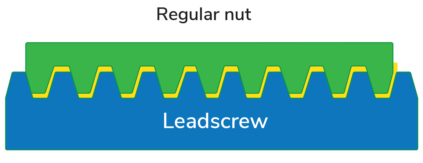
One of the biggest culprits of low accuracy, precision, and overall repeatability of the linear movement in a linear actuator is backlash. There are always slight tolerance differences between the thread cut of the nut and the thread of the screw, which is introduced during the manufacturing process. Meaning that the screw and the nut will never achieve a 100% perfect fit. There will always be small tolerance gaps between the two threads, otherwise known as backlash.
In a linear actuator, rotary motion is translated into linear motion with a use of a leadscrew and a nut. In this instance, the nut is embedded into the motor’s rotor, which pulls or pushes the leadscrew through the rotor, depending on which direction the motor rotates. As the rotor (or the nut) changes the direction of rotation, the rotor needs to travel over a certain distance--usually measured in arc minutes or seconds—before the other side of the thread fully engages (see fig. 2).
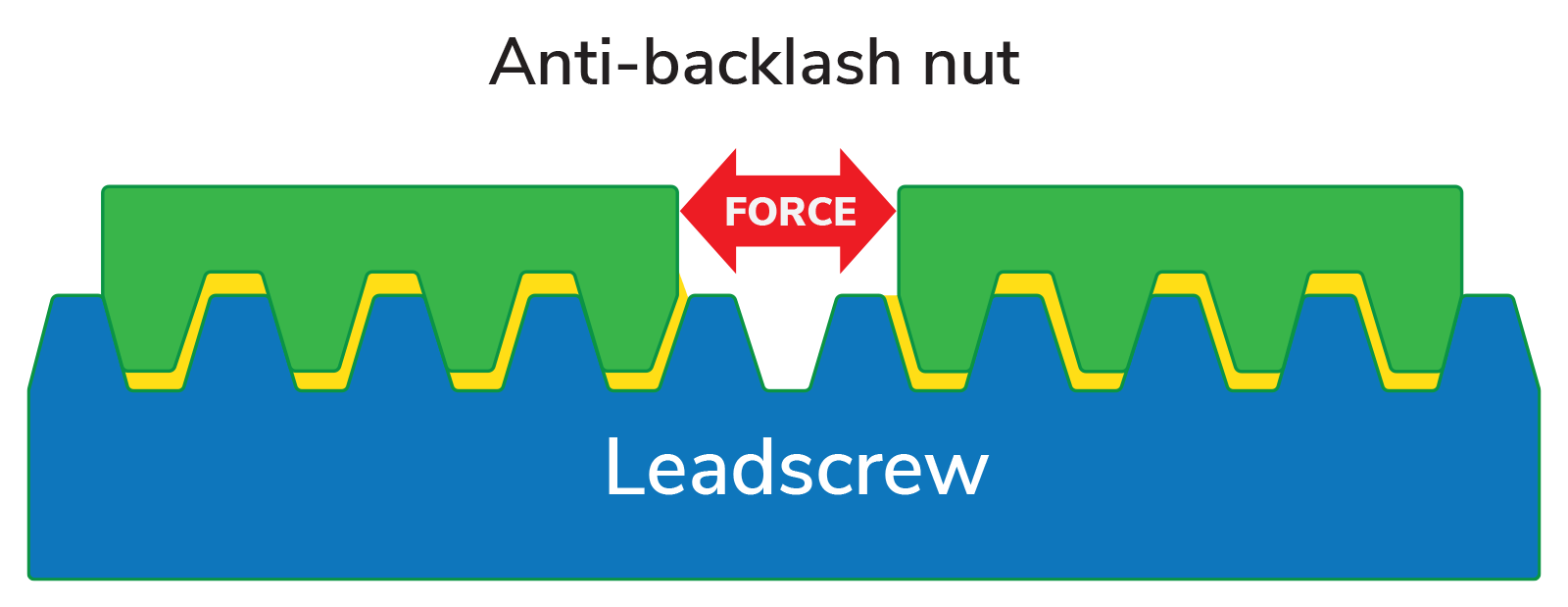
In order to reduce backlash, a mechanism is needed to minimize the gap between the two threads. This is usually accomplished with the use of an anti-backlash nut (see fig. 3). The anti-backlash nut is usually split into two or more parts, and force is applied between the parts in order to fill in the gaps between the two threads.
Of course, as with any added mechanism, there are other things to consider. The preload force needs to match or exceed the force that will be applied upon the nut for the backlash mechanism to function properly. If the applied force exceeds the preload force, the anti-backlash mechanism will compress, rendering the mechanism ineffective. Something to consider about these systems is that preload force increases friction and resistance between the two surfaces, which can reduce the maximum force output of the actuator.
The customer’s application required moving a significant load, which would need a significant amount of preload on the anti-backlash mechanism. However, due to the design restrictions of a captive linear actuator, where the nut is integrated with the rotor of the motor, conventional anti-backlash nut designs were not suitable. The backlash had to be reduced through different means.
Our proprietary design has an innovative and clever way to reduce the backlash, as well as setting the preload without using a conventional split nut. This allows it to be easily replicated while increasing reliability.
Ease of manufacturing and assembly to reduce the overall system cost
One of the biggest concerns with most product developers and manufacturers is the cost of the system. Most product developers need to meet certain price targets dictated by the marketplace, therefore the cost of individual components and the costs associated with manufacturing and assembly of the final product is very important.
We were able to help reduce costs in two significant ways. One, we have optimized the design of the motor for ease of manufacturing on our end, so we can pass the cost savings onto our customer. And two, we have optimized the motor to be easily installed by our customer on their production line. The motor does not require any additional setup or configuration. It’s a simple plug-and-play solution.
Manufacturers know that it’s easy to manufacture one unit, but it’s very difficult to manufacture the same unit in mass volume while still being reliable and delivering consistent performance. One unnecessary operation or component can significantly increase the time required to manufacture the motor. The problem is then multiplied by the volume of motors manufactured.
Our secret for consistent and reliable linear actuators lies within our proprietary anti-backlash mechanism. The design proves simple and easy to assemble on the manufacturing floor while delivering repeatable and consistent results. Our teams set the backlash per application so there is no further adjustment or setup needed by the customer.
The result
The end result is that the customer got exactly what they required: a high speed, high force linear actuator that delivered accurate and repeatable motion while being cost effective in the context of the overall system.
Learn more about how we can support you during the development of your next product. Talk to one of Motion Control Experts about your next development project.


Speak with one of our motion control experts about your next project.
Ready to start on your next product development project?
Let us know how we can help.